- 2000 Nissan Sentra
- 2001 Nissan Sentra
- 2002 Nissan Sentra
- 2003 Nissan Sentra
- 2004 Nissan Sentra
- 2005 Nissan Sentra
- 2006 Nissan Sentra
Serial Number List: VIN: 3N1BB51D1Y to 3N1CB51D6Y
Production year(s): 2000, 2001, 2002, 2003, 2004, 2005, 2006


Serial Number List: VIN: 3N1BB51D1Y to 3N1CB51D6Y
Production year(s): 2000, 2001, 2002, 2003, 2004, 2005, 2006
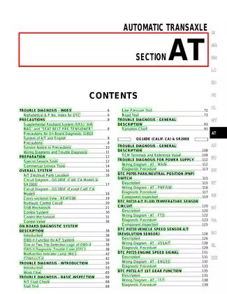
INDEX FOR DTC
Index for Trouble Codes
Alphabetical Index
DTC No. Index
PRECAUTIONS
Precautions for Supplemental Restraint System (SRS) “AIR BAG” and “SEAT BELT PRE-TENSIONER”
Precautions for OnBoardDiagnostic(OBD) System of A/T and Engine
Precautions for A/T Assembly and Control Valve Assembly Replacement
Service Notice or Precautions
Wiring Diagrams and Trouble Diagnosis
PREPARATION
Special Service Tools
Commercial Service Tools
A/T FLUID
Changing A/T Fluid
Checking A/T Fluid
A/T CONTROL SYSTEM
Cross-Sectional View
Shift Mechanism
TCM Function
CAN Communication
Input/Output Signal of TCM
Line Pressure Control
Shift Control
Lock-Up Control
ON BOARD DIAGNOSTIC (OBD) SYSTEM
Introduction
OBD-II Function for A/T System
One or Two Trip Detection Logic of OBD-II
OBD-II Diagnostic Trouble Code (DTC)
Malfunction Indicator Lamp (MIL)
TROUBLE DIAGNOSIS
DTC Inspection Priority Chart
Fail-Safe
How To Perform Trouble Diagnosis For Quick and Accurate Repair
A/T Electrical Parts Location
Circuit Diagram
Inspections Before Trouble Diagnosis
Check Before Engine is Started
Check at Idle
Cruise Test - Part 1
Cruise Test - Part 2
Cruise Test - Part 3
Shift Schedule
Symptom Chart
TCM Input/Output Signal Reference Values
CONSULT-II Function (TCM)
CONSULT-II
Diagnostic Procedure Without CONSULT-II
DTC U1000 CAN COMMUNICATION LINE
Description
On Board Diagnosis Logic
Possible Cause
DTC Confirmation Procedure
Wiring Diagram — AT — CAN
Diagnostic Procedure
DTC P0500 VEHICLE SPEED SENSOR MTR
Description
On Board Diagnosis Logic
Possible Cause
DTC Confirmation Procedure
Wiring Diagram — AT — VSS/AT
Diagnostic Procedure
DTC P0613 TCM PROCESSOR
Description
On Board Diagnosis Logic
Possible Cause
DTC Confirmation Procedure
Diagnostic Procedure
DTC P0705 PARK/NEUTRAL POSITION SWITCH
Description
On Board Diagnosis Logic
Possible Cause
DTC Confirmation Procedure
Wiring Diagram — AT — PNP/SW
Diagnostic Procedure
Component Inspection
DTC P0710 A/T FLUID TEMPERATURE SENSOR
Description
On Board Diagnosis Logic
Possible Cause
DTC Confirmation Procedure
Wiring Diagram — AT — FTS
Diagnostic Procedure
Component Inspection
DTC P0711 FLUID TEMPERATURE SENSOR PERFORMANCE
Description
On Board Diagnosis Logic
Possible Cause
DTC Confirmation Procedure
Wiring Diagram — AT — FTSP
Diagnostic Procedure
Component Inspection
DTC P0717 TURBINE REVOLUTION SENSOR CIRCUIT
Description
On Board Diagnosis Logic
Possible Cause
DTC Confirmation Procedure
Wiring Diagram — AT — TRSC
Diagnostic Procedure
Component Inspection
DTC P0720 VEHICLE SPEED SENSOR A/T (REVOLUTION SENSOR)
Description
On Board Diagnosis Logic
Possible Cause
DTC Confirmation Procedure
Wiring Diagram — AT — VSS/ATC
Diagnostic Procedure
Component Inspection
DTC P0725 ENGINE SPEED INPUT CIRCUIT PERFORMANCE
Description
On Board Diagnosis Logic
Possible Cause
DTC Confirmation Procedure
Wiring Diagram — AT — ESS
Diagnostic Procedure
Component Inspection
DTC P0731 A/T 1ST GEAR FUNCTION
Description
On Board Diagnosis Logic
Possible Cause
DTC Confirmation Procedure
Wiring Diagram — AT — 1STSIG
Diagnostic Procedure
DTC P0732 A/T 2ND GEAR FUNCTION
Description
On Board Diagnosis Logic
Possible Cause
DTC Confirmation Procedure
Wiring Diagram — AT — 2NDSIG
Diagnostic Procedure
Component Inspection
DTC P0733 A/T 3RD GEAR FUNCTION
Description
On Board Diagnosis Logic
Possible Cause
DTC Confirmation Procedure
Wiring Diagram — AT — 3RDSIG
Diagnostic Procedure
Component Inspection
DTC P0734 A/T 4TH GEAR FUNCTION
Description
On Board Diagnosis Logic
Possible Cause
DTC Confirmation Procedure
Wiring Diagram — AT — 4THSIG
Diagnostic Procedure
Component Inspection
DTC P0735 A/T 5TH GEAR FUNCTION
Description
On Board Diagnosis Logic
Possible Cause
DTC Confirmation Procedure
Wiring Diagram — AT — 5THSIG
Diagnostic Procedure
Component Inspection
DTC P0744 A/T TCC S/V FUNCTION (LOCK-UP)
Description
On Board Diagnosis Logic
Possible Cause
DTC Confirmation Procedure
Wiring Diagram — AT — TCCSIG
Diagnostic Procedure
Component Inspection
DTC P0745 LINE PRESSURE SOLENOID VALVE
Description
On Board Diagnosis Logic
Possible Cause
DTC Confirmation Procedure
Wiring Diagram — AT — LPSV
Diagnostic Procedure
Component Inspection
DTC P0750 SHIFT SOLENOID VALVE A
Description
On Board Diagnosis Logic
Possible Cause
DTC Confirmation Procedure
Wiring Diagram — AT — SSV/A
Diagnostic Procedure
Component Inspection
The price of this manual, handbooks, and repair guides are not set by our marketplace, but by the seller of the manuals themselves, so it is possible that the same manual is offered at a different price on another page here. Please compare prices before deciding to purchase.
For many of our manuals, there are comments and ratings from other users at the end of the detail page to make your purchase decision easier. Please leave a review after your purchase to help other users make their purchasing decision.
Don't hesitate and download the repair manual you need now. You get a lifetime guarantee for the download, as described in our FAQs at FAQ Link.
To contact the seller of the manual, please use our contact form at Contact Form Link and we will forward your request or take care of it directly.
This policy contains information about your privacy. By posting, you are declaring that you understand this policy:
This policy is subject to change at any time and without notice.
These terms and conditions contain rules about posting comments. By submitting a comment, you are declaring that you agree with these rules:
Failure to comply with these rules may result in being banned from submitting further comments.
These terms and conditions are subject to change at any time and without notice.
Comments