- Nissan Maxima SE (2004)
- Nissan Maxima SL (2004)
- Nissan Maxima 3.5 SE (2005)
- Nissan Maxima 3.5 SL (2005)
- Nissan Maxima SE (2006)
- Nissan Maxima SL (2006)
- Nissan Maxima SE (2007)
- Nissan Maxima SL (2007)
- Nissan Maxima SE (2008)
- Nissan Maxima SL (2008)
- Nissan Maxima SE (2009)
- Nissan Maxima SL (2009)


2004-2009 Nissan Maxima Automatic Transaxle manual
Models covered in this manual:
File specifications
File type: ZIP
Language: English
Printable: Yes
Estimated download time: 5.43 Minutes
$7.99
Pay with Bitcoin
Product Information
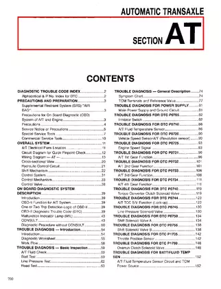
Table of Contents
INDEX FOR DTC
- Alphabetical Index
- DTC No. Index
PRECAUTIONS
- Precautions for Supplemental Restraint System (SRS) “AIR BAG” and “SEAT BELT PRE-TENSIONER”
- Precautions for OnBoardDiagnostic(OBD)System of A/T and Engine
- Precautions for A/T Assembly or TCM Replacement
- Precautions
- Service Notice or Precautions
- Wiring Diagrams and Trouble Diagnosis
PREPARATION
- Special Service Tools
- Commercial Service Tools
A/T FLUID
- Changing A/T Fluid
- Checking A/T Fluid
A/T CONTROL SYSTEM
- Cross-Sectional View
- Shift Mechanism
- TCM Function
- CAN Communication
- Input/Output Signal of TCM
- Line Pressure Control
- Shift Control
- Lock-Up Control
ON BOARD DIAGNOSTIC (OBD) SYSTEM
- Introduction
- OBD-II Function for A/T System
- One or Two Trip Detection Logic of OBD-II
- OBD-II Diagnostic Trouble Code (DTC)
- Malfunction Indicator Lamp (MIL)
TROUBLE DIAGNOSIS
- DTC Inspection Priority Chart
- Fail-Safe
- How To Perform Trouble Diagnosis For Quick and Accurate Repair
- A/T Electrical Parts Location
CIRCUIT DIAGRAM
- Inspections Before Trouble Diagnosis
- Check Before Engine is Started
- Check at Idle
- Cruise Test - Part 1
- Cruise Test - Part 2
- Cruise Test - Part 3
- Shift Schedule
- Symptom Chart
- TCM Input/Output Signal Reference Values
- CONSULT-II Function (TCM)
- Diagnostic Procedure Without CONSULT-II
DTC U1000 CAN COMMUNICATION LINE
- Description
- On Board Diagnosis Logic
- Possible Cause
- DTC Confirmation Procedure
- Wiring Diagram — AT — CAN
- Diagnostic Procedure
DTC P0500 VEHICLE SPEED SENSOR MTR
- Description
- On Board Diagnosis Logic
- Possible Cause
- DTC Confirmation Procedure
- Wiring Diagram — AT — VSSAT
- Diagnostic Procedure
DTC P0613 TCM PROCESSOR
- Description
- On Board Diagnosis Logic
- Possible Cause
- DTC Confirmation Procedure
- Diagnostic Procedure
DTC P0705 PARK/NEUTRAL POSITION SWITCH
- Description
- On Board Diagnosis Logic
- Possible Cause
- DTC Confirmation Procedure
- Wiring Diagram — AT — PNP/SW
- Diagnostic Procedure
- Component Inspection
DTC P0710 A/T FLUID TEMPERATURE SENSOR CIRCUIT
- Description
- On Board Diagnosis Logic
- Possible Cause
- DTC Confirmation Procedure
- Wiring Diagram — AT — FTS
- Diagnostic Procedure
- Component Inspection
DTC P0711 FLUID TEMPERATURE SENSOR PERFORMANCE
- Description
- On Board Diagnosis Logic
- Possible Cause
- DTC Confirmation Procedure
- Wiring Diagram — AT — FTSP
- Diagnostic Procedure
- Component Inspection
DTC P0717 TURBINE REVOLUTION SENSOR CIRCUIT
- Description
- On Board Diagnosis Logic
- Possible Cause
- DTC Confirmation Procedure
- Wiring Diagram — AT — TRSC
- Diagnostic Procedure
DTC P0722 VEHICLE SPEED SENSOR A/T (REVOLUTION SENSOR)
- Description
- On Board Diagnosis Logic
- Possible Cause
- DTC Confirmation Procedure
- Wiring Diagram — AT — VSSATC
- Diagnostic Procedure
- Component Inspection
DTC P0726 ENGINE SPEED INPUT CIRCUIT PERFORMANCE
- Description
- On Board Diagnosis Logic
- Possible Cause
- DTC Confirmation Procedure
- Wiring Diagram — AT — 1STSIG
- Diagnostic Procedure
DTC P0731 1ST GEAR FUNCTION
- Description
- On Board Diagnosis Logic
- Possible Cause
- DTC Confirmation Procedure
- Wiring Diagram — AT — 1STSIG
- Diagnostic Procedure
DTC P0732 A/T 2ND GEAR FUNCTION
- Description
- On Board Diagnosis Logic
- Possible Cause
- DTC Confirmation Procedure
- Wiring Diagram — AT — 2NDSIG
- Diagnostic Procedure
DTC P0733 A/T 3RD GEAR FUNCTION
- Description
- On Board Diagnosis Logic
- Possible Cause
- DTC Confirmation Procedure
- Wiring Diagram — AT — 3RDSIG
- Diagnostic Procedure
DTC P0734 A/T 4TH GEAR FUNCTION
- Description
- On Board Diagnosis Logic
- Possible Cause
- DTC Confirmation Procedure
- Wiring Diagram — AT — 4THSIG
- Diagnostic Procedure
DTC P0735 A/T 5TH GEAR FUNCTION
- Description
- On Board Diagnosis Logic
- Possible Cause
- DTC Confirmation Procedure
- Wiring Diagram — AT — 5THSIG
- Diagnostic Procedure
DTC P0744 A/T TCC S/V FUNCTION (LOCK-UP)
- Description
- On Board Diagnosis Logic
- Possible Cause
- DTC Confirmation Procedure
- Wiring Diagram — AT — TCCSIG
- Diagnostic Procedure
- Component Inspection
DTC P0745 PRESSURE CONTROL SOLENOID VALVE A (LINE PRESSURE)
- Description
- On Board Diagnosis Logic
- Possible Cause
- DTC Confirmation Procedure
- Wiring Diagram — AT — PC/A
- Diagnostic Procedure
- Component Inspection
DTC P0750 SHIFT SOLENOID VALVE A
- Description
- On Board Diagnosis Logic
- Possible Cause
- DTC Confirmation Procedure
- Wiring Diagram — AT — SSV/A
- Diagnostic Procedure
- Component Inspection
DTC P0755 SHIFT SOLENOID VALVE B
- Description
- On Board Diagnosis Logic
- Possible Cause
- DTC Confirmation Procedure
- Wiring Diagram — AT — SSV/B
- Diagnostic Procedure
- Component Inspection
DTC P0760 SHIFT SOLENOID VALVE C
- Description
- On Board Diagnosis Logic
- Possible Cause
- DTC Confirmation Procedure
- Wiring Diagram — AT — SSV/C
- Diagnostic Procedure
- Component Inspection
DTC P0762 SHIFT SOLENOID VALVE C STUCK ON
- Description
- On Board Diagnosis Logic
- Possible Cause
- DTC Confirmation Procedure
- Wiring Diagram — AT — SSV/CS
- Diagnostic Procedure
- Component Inspection
DTC P0765 SHIFT SOLENOID VALVE D
- Description
- On Board Diagnosis Logic
- Possible Cause
- DTC Confirmation Procedure
- Wiring Diagram — AT — SSV/D
- Diagnostic Procedure
- Component Inspection
DTC P0770 SHIFT SOLENOID VALVE E
- Description
- On Board Diagnosis Logic
- Possible Cause
- DTC Confirmation Procedure
- Wiring Diagram — AT — SSV/E
- Diagnostic Procedure
- Component Inspection
DTC P0775 PRESSURE CONTROL SOLENOID VALVE C (TCC AND SHIFT PRESSURE)
- Description
- On Board Diagnosis Logic
- Possible Cause
- DTC Confirmation Procedure
- Wiring Diagram — AT — PC/C
- Diagnostic Procedure
- Component Inspection
DTC P0797 PRESSURE CONTROL SOLENOID VALVE C STUCK ON
- Description
- On Board Diagnosis Logic
- Possible Cause
- DTC Confirmation Procedure
- Wiring Diagram — AT — PC/CS
- Diagnostic Procedure
- Component Inspection
DTC P0826 MANUAL MODE SWITCH CIRCUIT
- Description
- On Board Diagnosis Logic
- Possible Cause
- DTC Confirmation Procedure
- Wiring Diagram — AT — PC/CS
- Diagnostic Procedure
- Component Inspection
CONSULT-II Reference Value in Data Monitor Mode
- On Board Diagnosis Logic
- Possible Cause
- DTC Confirmation Procedure
- Wiring Diagram — AT — SSV/E
- Diagnostic Procedure
- Component Inspection
DTC P0882 TCM POWER INPUT SIGNAL
- Description
- On Board Diagnosis Logic
- Possible Cause
- DTC Confirmation Procedure
- Wiring Diagram — AT — PWR/IN
- Diagnostic Procedure
- Component Inspection
DTC P1226 ELECTRIC THROTTLE CONTROL SYSTEM
- Description
- On Board Diagnosis Logic
- Possible Cause
- DTC Confirmation Procedure
- Wiring Diagram — AT — PWR/IN
- Diagnostic Procedure
- Component Inspection
TROUBLE DIAGNOSIS FOR SYMPTOMS
- A/T CHECK Indicator Lamp does not come on
- Engine Cannot Be Started In “P” or “N” Position
- In “P” Position, Vehicle Moves When Pushed
- Large Shock (“N” to “D” Position)
- Vehicle Does Not Creep Forward In “D” Position
- Vehicle Cannot Be Started From D1
- A/T Does Not Shift: D1 ⇒ D2
- A/T Does Not Shift: D2 ⇒ D3
- A/T Does Not Shift: D3 ⇒ D4
- A/T Does Not Shift: D4 ⇒ D5
- A/T Does Not Perform Lock-up
- Lock-up is Not Released
- Cannot Be Changed to Manual Mode
- A/T Does Not Shift: 5th gear ⇒ 4th gear
- A/T Does Not Shift: 4th gear ⇒ 3rd gear
- A/T Does Not Shift: 3rd gear ⇒ 2nd gear
- A/T Does Not Shift: 2nd gear ⇒ 1st gear
- Vehicle Does Not Decelerate By Engine Brake
- TCM Self-diagnosis Does Not Activate
SHIFT CONTROL SYSTEM
- Control Device
- Control Cable
- Adjustment
A/T SHIFT LOCK SYSTEM
- Description
- Shift Lock System Electrical Parts Location
- Wiring Diagram — AT — SHIFT
- Shift Lock Control Unit Reference Values
- Component Inspection
- Diagnostic Procedure
ON-VEHICLE SERVICE
- Revolution Sensor Replacement
- Turbine Revolution Sensor Replacement
- Park/Neutral Position (PNP) Switch Adjustment
- ATF Cooler
- ATF Cooler Valve
- Control Cable Adjustment
ASSEMBLY
- Assembly (1)
- Assembly (2)
- Adjustment
TRANSAXLE ASSEMBLY
- Removal and Installation
INSPECTION AFTER REMOVAL
- Components
OVERHAUL
- Components
- Locations of Needle Bearings, Bearing Races and Thrust Washers
- Disassembly
- Disassembly
REPAIR FOR COMPONENT PARTS
- Oil Pump, 2nd Coast Brake & 2nd Brake
- One Way Clutch Outer Race Sub Assembly & 2nd Coast Brake Hub & One Way Clutch No.1
- Transaxle Case Cover & B5 Brake
- Differential Gear Assembly
SERVICE DATA AND SPECIFICATIONS (SDS)
- General Specifications
- Shift Schedule
- Line Pressure
- Stall Speed
- Solenoid Valves
- Clutch and Brakes
- Final Drive
- A/T Fluid Temperature Sensor
- Turbine Revolution Sensor
- Revolution Sensor
- The price of this manual, handbooks, and repair guides are set by the seller, so please compare prices before deciding to purchase.
- Ratings and comments from other users are available on the detail page to help with your purchasing decision.
- Don't hesitate and download the repair manual you need now. You get a lifetime guarantee for the download.
- To contact the seller of the manual, please use our contact form and we will forward your request or take care of it directly.
How to Download Your Manual - Delivery Policy
Within a minute after completing the payment process, you will receive two emails from us. One for the completed payment and another with the download link. The download link is valid for 3 days.
Lifetime Guarantee
Manuals frequently bought together

Add Comment
Insert Bullet List
Please enter at least one item.
Item:
Item:
Item:
Item:
Item:
Insert Numeric List
Please enter at least one item.
Item:
Item:
Item:
Item:
Item:
Insert Link
Please enter the link of the website
Optionally you can add display text
Insert Email
Please enter the email address
Optionally add any display text
Insert Image
Please enter the link of the image
Insert YouTube Video
Please enter the link of the video
Privacy Policy
This policy contains information about your privacy. By posting, you are declaring that you understand this policy:
- Your name, rating, website address, town, country, state and comment will be publicly displayed if entered.
- Aside from the data entered into these form fields, other stored data about your comment will include:
- Your IP address (not displayed)
- The time/date of your submission (displayed)
- Your email address will not be shared. It is collected for only two reasons:
- Administrative purposes, should a need to contact you arise.
- To inform you of new comments, should you subscribe to receive notifications.
- A cookie may be set on your computer. This is used to remember your inputs. It will expire by itself.
This policy is subject to change at any time and without notice.
Terms and Conditions
These terms and conditions contain rules about posting comments. By submitting a comment, you are declaring that you agree with these rules:
- Although the administrator will attempt to moderate comments, it is impossible for every comment to have been moderated at any given time.
- You acknowledge that all comments express the views and opinions of the original author and not those of the administrator.
- You agree not to post any material which is knowingly false, obscene, hateful, threatening, harassing or invasive of a person's privacy.
- The administrator has the right to edit, move or remove any comment for any reason and without notice.
Failure to comply with these rules may result in being banned from submitting further comments.
These terms and conditions are subject to change at any time and without notice.
{"commentics_url":"\/\/www.repairloader.com\/comments\/","page_id":188548,"enabled_country":false,"country_id":0,"enabled_state":false,"state_id":0,"enabled_upload":false,"maximum_upload_amount":3,"maximum_upload_size":5,"maximum_upload_total":5,"captcha":true,"captcha_url":"https:\/\/www.repairloader.com\/comments\/frontend\/index.php?route=main\/form\/captcha&page_id=188548","cmtx_wait_for_comment":"cmtx_wait_for_comment","lang_error_file_num":"A maximum of %d files are allowed to be uploaded","lang_error_file_size":"Please upload files no bigger than %.1f MB in size","lang_error_file_total":"The total size of all files must be less than %.1f MB","lang_error_file_type":"Only image file types are allowed to be uploaded","lang_text_loading":"Loading ..","lang_placeholder_country":"Country","lang_placeholder_state":"State","lang_text_country_first":"Please select a country first","lang_button_submit":"Add Comment","lang_button_preview":"Preview","lang_button_remove":"Remove","lang_button_processing":"Please Wait.."}
{"commentics_url":"\/\/www.repairloader.com\/comments\/","language":"english"}
Comments