Enter a keyword to search over 12,000 manuals:
2007 Infiniti G35 Sedan Automatic Drive Positioner manual Preview image 1
2007 Infiniti G35 Sedan Automatic Drive Positioner manual Preview image 2
2007 Infiniti G35 Sedan Automatic Drive Positioner manual Preview image 3
2007 Infiniti G35 Sedan Automatic Drive Positioner manual Preview image 4
2007 Infiniti G35 Sedan Automatic Drive Positioner manual Preview image 5
2007 Infiniti G35 Sedan Automatic Drive Positioner manual Preview image 6

2007 Infiniti G35 Sedan Automatic Drive Positioner manual

Models covered in this manual:

G35 Sedan / Infiniti (Nissan)

  • Infiniti G35 Sedan Journey
  • Infiniti G35 Sedan x AWD
  • Infiniti G35 Sedan Sport
  • Infiniti G35 Sedan 6MT (Manual Transmission)

Production year(s): 2007
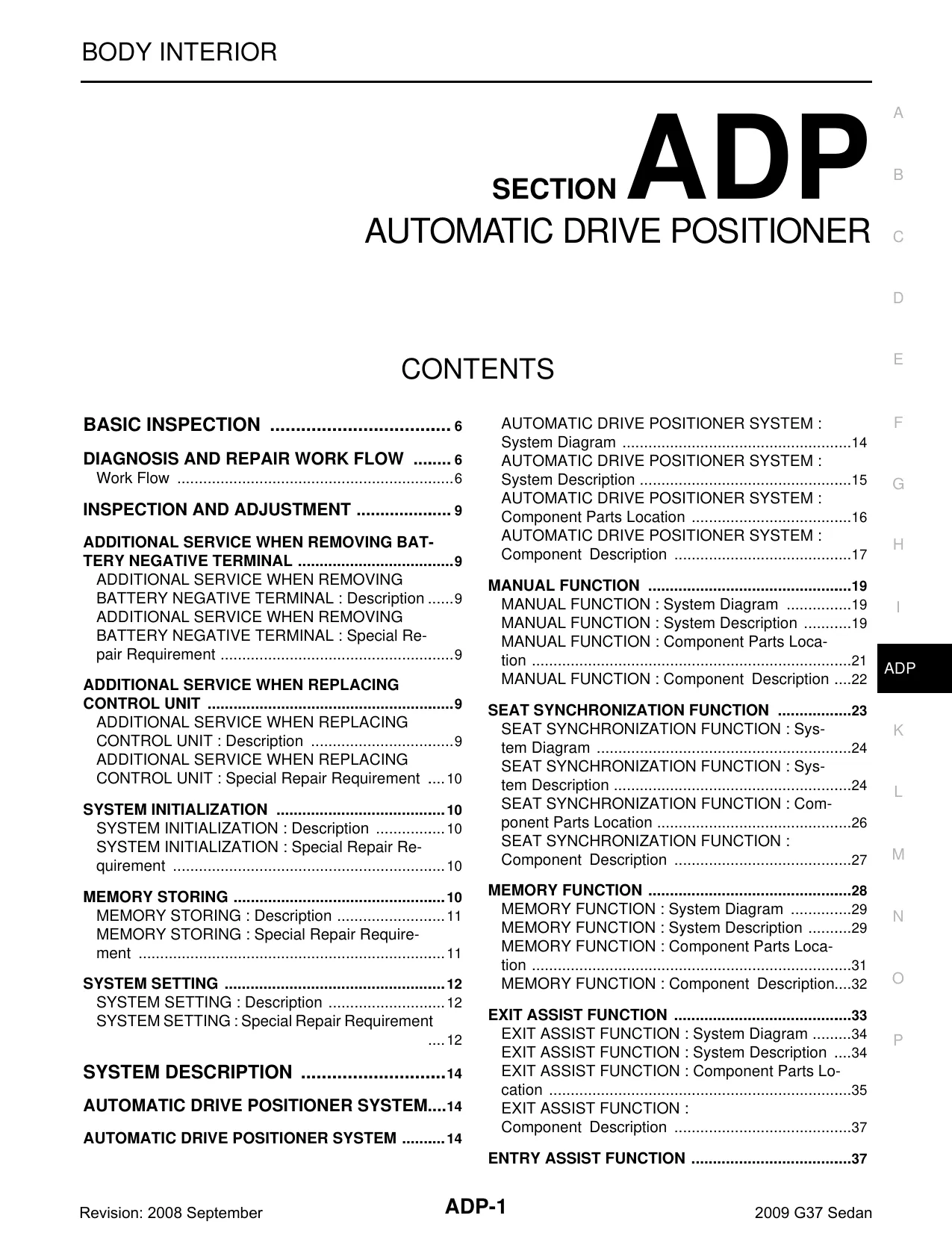
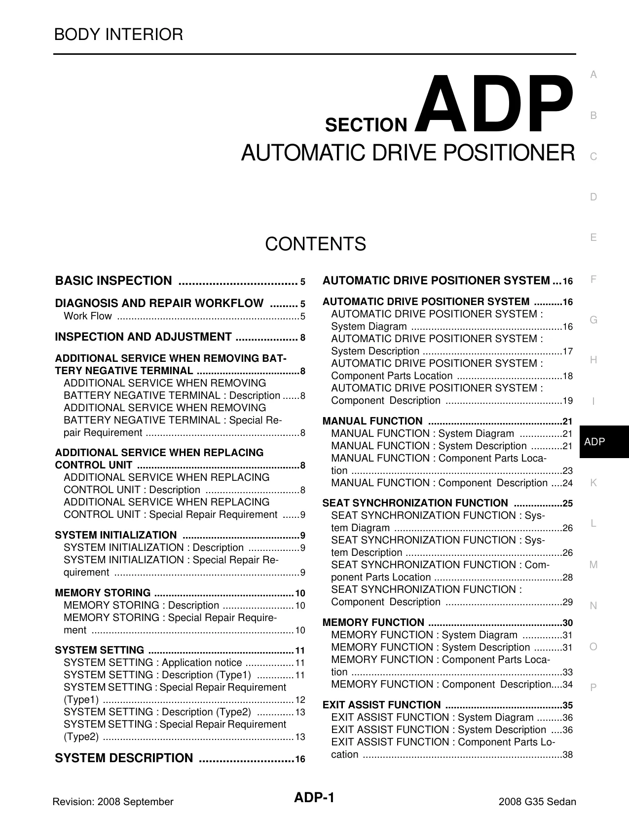
File specifications

File size: 81.20 MB
File type: ZIP
Language: English

Printable: Yes
Estimated download time: 1.66 Minutes
$18.99 Instant Download

Pay with Bitcoin

Product Information

Table of Contents

  1. BASIC INSPECTION

    • Basic Inspection Procedures
  2. DIAGNOSIS AND REPAIR WORKFLOW

    • Workflow Overview
  3. INSPECTION AND ADJUSTMENT

    • Inspection Procedures
    • Adjustment Procedures
  4. ADDITIONAL SERVICE WHEN REMOVING BATTERY NEGATIVE TERMINAL

    • Description
    • Special Repair Requirement
  5. ADDITIONAL SERVICE WHEN REPLACING CONTROL UNIT

    • Description
    • Special Repair Requirement
  6. SYSTEM INITIALIZATION

    • Description
    • Special Repair Requirement
  7. MEMORY STORING

    • Description
    • Special Repair Requirement
  8. SYSTEM SETTING

    • Description
    • Special Repair Requirement
  9. FUNCTION DIAGNOSIS

    • System Description
    • System Diagram
  10. AUTOMATIC DRIVE POSITIONER SYSTEM

    • System Diagram
    • Component Parts Location
    • System Description
  11. MANUAL FUNCTION

    • System Diagram
    • System Description
    • Component Parts Location
    • Component Description
  12. SEAT SYNCHRONIZATION FUNCTION

    • System Diagram
    • System Description
    • Component Parts Location
    • Component Description
  13. MEMORY FUNCTION

    • System Diagram
    • System Description
    • Component Parts Location
    • Component Description
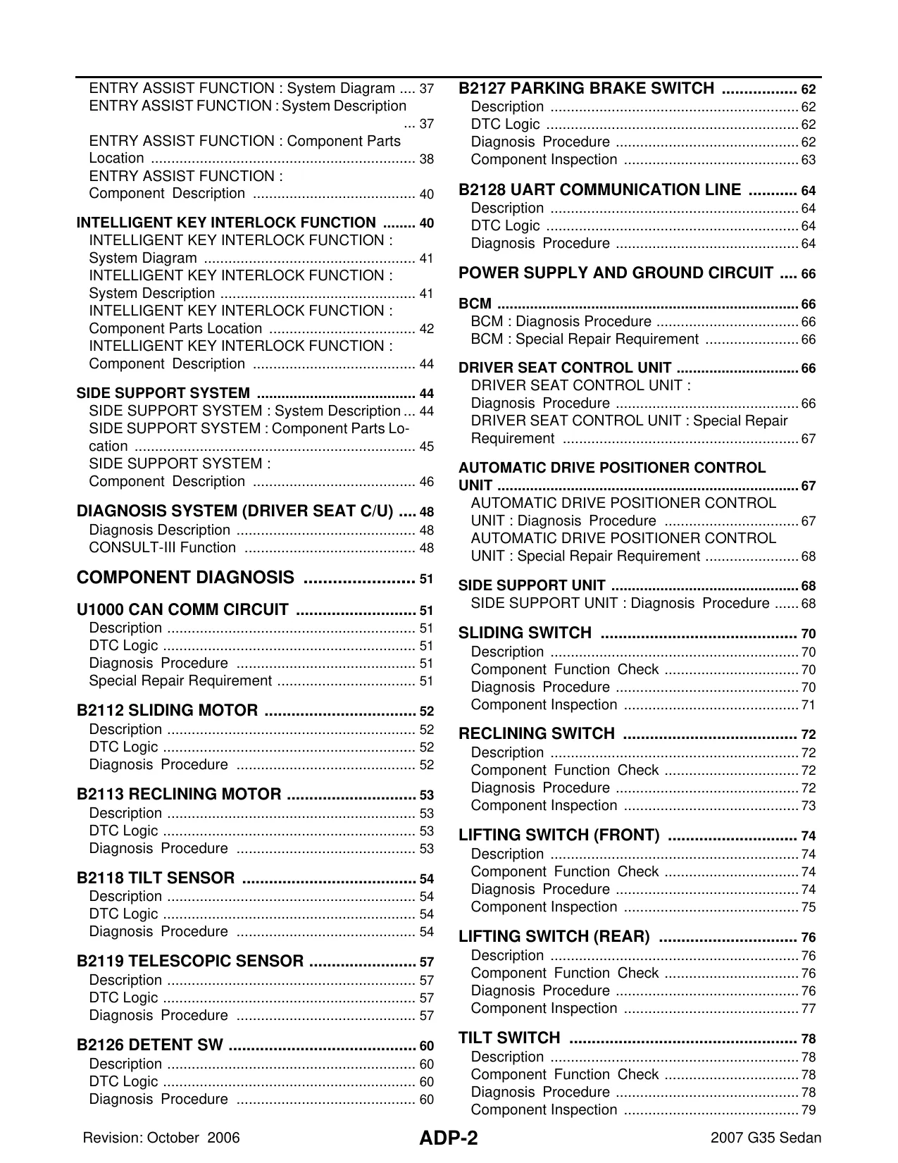
  14. EXIT ASSIST FUNCTION

    • System Diagram
    • System Description
    • Component Parts Location
    • Component Description
  15. ENTRY ASSIST FUNCTION

    • System Diagram
    • System Description
    • Component Parts Location
    • Component Description
  16. INTELLIGENT KEY INTERLOCK FUNCTION

    • System Diagram
    • System Description
    • Component Parts Location
    • Component Description
  17. SIDE SUPPORT SYSTEM

    • System Description
    • Component Parts Location
    • Component Description
  18. DIAGNOSIS SYSTEM (DRIVER SEAT CONTROL UNIT)

    • Diagnosis Description
    • CONSULT-II Function
  19. COMPONENT DIAGNOSIS

    • U1000 CAN Communication Circuit
    • B2112 Sliding Motor
    • B2113 Reclining Motor
    • B2118 Tilt Sensor
    • B2119 Telescopic Sensor
    • B2126 Detent Switch
    • B2127 Parking Brake Switch
    • B2128 UART Communication Line
  20. POWER SUPPLY AND GROUND CIRCUIT

    • BCM Diagnosis Procedure
    • Driver Seat Control Unit Diagnosis Procedure
  21. AUTOMATIC DRIVE POSITIONER CONTROL UNIT

    • Diagnosis Procedure
    • Special Repair Requirement
  22. SIDE SUPPORT UNIT

    • Diagnosis Procedure
  23. SLIDING SWITCH

    • Description
    • Component Function Check
    • Diagnosis Procedure
    • Component Inspection
  24. RECLINING SWITCH

    • Description
    • Component Function Check
    • Diagnosis Procedure
    • Component Inspection
  25. LIFTING SWITCH (FRONT)

    • Description
    • Component Function Check
    • Diagnosis Procedure
    • Component Inspection
  26. LIFTING SWITCH (REAR)

    • Description
    • Component Function Check
    • Diagnosis Procedure
    • Component Inspection
  27. TILT SWITCH

    • Description
    • Component Function Check
    • Diagnosis Procedure
    • Component Inspection
  28. TELESCOPIC SWITCH

    • Description
    • Component Function Check
    • Diagnosis Procedure
    • Component Inspection
  29. SEAT MEMORY SWITCH

    • Description
    • Component Function Check
    • Diagnosis Procedure
    • Component Inspection
  30. DOOR MIRROR REMOTE CONTROL SWITCH

    • Description
    • Component Function Check
    • Diagnosis Procedure
    • Component Inspection
  31. CHANGEOVER SWITCH

    • Description
    • Component Function Check
    • Diagnosis Procedure
    • Component Inspection
  32. MIRROR SWITCH

    • Description
    • Component Function Check
    • Diagnosis Procedure
    • Component Inspection
  33. POWER SEAT SWITCH GROUND CIRCUIT

    • Diagnosis Procedure
  34. SIDE SUPPORT SWITCH

    • Description
    • Component Function Check
    • Diagnosis Procedure
    • Component Inspection
  35. DETENTION SWITCH

    • Description
    • Component Function Check
    • Diagnosis Procedure
    • Component Inspection
  36. PARKING BRAKE SWITCH

    • Description
    • Component Function Check
    • Diagnosis Procedure
    • Component Inspection
  37. FRONT DOOR SWITCH (DRIVER SIDE)

    • Description
    • Component Function Check
    • Diagnosis Procedure
    • Component Inspection
  38. SLIDING SENSOR

    • Description
    • Component Function Check
    • Diagnosis Procedure
    • Component Inspection
  39. RECLINING SENSOR

    • Description
    • Component Function Check
    • Diagnosis Procedure
    • Component Inspection
  40. LIFTING SENSOR (FRONT)

    • Description
    • Component Function Check
    • Diagnosis Procedure
    • Component Inspection
  41. LIFTING SENSOR (REAR)

    • Description
    • Component Function Check
    • Diagnosis Procedure
    • Component Inspection
  42. TILT SENSOR

    • Description
    • Component Function Check
    • Diagnosis Procedure
    • Component Inspection
  43. TELESCOPIC SENSOR

    • Description
    • Component Function Check
    • Diagnosis Procedure
    • Component Inspection
  44. MIRROR SENSOR

    • Driver Side: Description, Component Function Check, Diagnosis Procedure
    • Passenger Side: Description, Component Function Check, Diagnosis Procedure
  45. SLIDING MOTOR

    • Description
    • Component Function Check
    • Diagnosis Procedure
    • Component Inspection
  46. RECLINING MOTOR

    • Description
    • Component Function Check
    • Diagnosis Procedure
    • Component Inspection
  47. LIFTING MOTOR (FRONT)

    • Description
    • Component Function Check
    • Diagnosis Procedure
    • Component Inspection
  48. LIFTING MOTOR (REAR)

    • Description
    • Component Function Check
    • Diagnosis Procedure
    • Component Inspection
  49. TILT MOTOR

    • Description
    • Component Function Check
    • Diagnosis Procedure
    • Component Inspection
  50. TELESCOPIC MOTOR

    • Description
    • Component Function Check
    • Diagnosis Procedure
    • Component Inspection
  51. DOOR MIRROR MOTOR

    • Description
    • Component Function Check
    • Diagnosis Procedure
    • Component Inspection
  52. SIDE SUPPORT UNIT

    • Description
    • Component Function Check
    • Diagnosis Procedure
    • Component Inspection
  53. ECU DIAGNOSIS

    • Automatic Drive Positioner Control Unit: Reference Value, Wiring Diagram, Fail Safe, DTC Index
    • BCM (Body Control Module): Reference Value, Wiring Diagram, Fail Safe, DTC Index
  54. SYMPTOM DIAGNOSIS

    • Symptom Table
  55. NORMAL OPERATING CONDITION

    • Description
  56. PRECAUTION

    • Precaution for Supplemental Restraint System (SRS) "Air Bag" and "Seat Belt Pre-Tensioner"
    • Service Precaution
    • Work Precaution
  57. ON-VEHICLE MAINTENANCE

    • Pre-Inspection for Diagnostic
    • Basic Inspection
  58. ON-VEHICLE REPAIR

    • Exploded View and Removal/Installation of: Driver Seat Control Unit, Automatic Drive Positioner Control Unit, Seat Memory Switch, Power Seat Switch, Side Support Switch, Tilt & Telescopic Switch

How to Download Your Manual - Delivery Policy

Instant delivery: Download link will appear on the checkout page after your payment is complete.
Within a minute after completing the payment process, you will receive two emails from us. One for the completed payment and another with the download link. The download link is valid for 3 days.
Lifetime Guarantee
Welcome to our Reviews Section! We value your feedback and would love to hear about your experience with our product. Thank you for taking the time to review!

Add Comment

* Required information
1000
Captcha Image
Powered by Commentics

Comments

No comments yet. Be the first!